Used to export your Structural
analytical data to the
STAAD.Pro analysis program. The data will be
presented in a format that the analysis program can use.
Used to export your Structural
analytical data to the
STAAD.Pro analysis program. The data will be
presented in a format that the analysis program can use.
Accessed from:
Design Parameters
Information
Design parameters are values assigned to structural
members. The specific parameters are dependent on which
design code or standard is chosen. When a
design code is chosen, the associated parameters are initialized with default
values. These are then applied to Structural members by selecting members
individually or as a selection set.
The
Structural discipline relies on the OpenSTAAD API as a
means of reading and writing STAAD.Pro
*.std files. OpenSTAAD provides the files that
define both the available design codes and the associated design parameters.
The available codes that the OpenSTAAD API supports are
found in the settings file
codes.ini. This file is located in the OpenSTAAD
folder:
\\OpenBuildings CONNECT
Edition\Designer\Assemblies\OpenStaad\Data
While it is possible to read this file directly, any
access of values within it should be done solely through the OpenSTAAD API.
References within
codes.ini point to supporting
*.ini files where available design parameters and
their default values are defined.
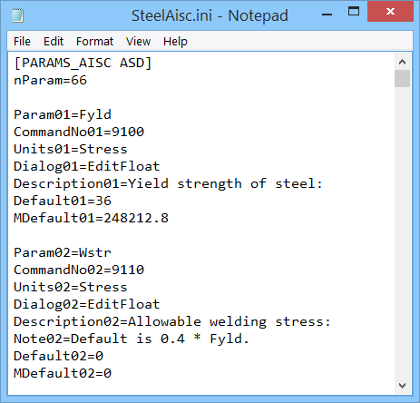
For instance, the
AISC ASD code references the parameters file
SteelAisc.ini. The parameters files referenced
list the parameters that apply to their corresponding design codes along with
their default values.
The entries in
SteelAisc.ini correspond to the listed Design
Parameters:
|
*.ini File Entry
|
Design Options tab Design Parameter
|
- Param01=Fyld
- CommandNo01=9100
- Units01=Stress
- Dialog01=EditFloat
- Description01=Yield strength of steel:
- Default01=36
- MDefault01=248212.8
|
Yield Strength of Steel
|
- Param04=Ly
- CommandNo04=9130
- Units04=Length
- Dialog04=EditFloat
- Description04=Length in local Y axis for
slenderness value KL/r:
- Note04=Default is selected beam's length.
- Default04=0
- MDefault04=0
|
Slenderness Length Ly
|
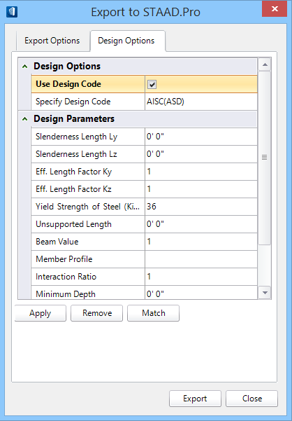
Design Options
tab
| Setting | Description |
|---|
| Design Options
|
- Use
Design Code — When on, select the available design codes from the
drop list. When off, design codes are not used.
-
Specify Design Code — When on, all
options on the Design Options dialog tab are enabled.
|
| Design Parameters
|
-
Slenderness Length Ly:
- Eff.
Length Factor Ky:
- Yield
Strength of Steel:
- Beam
Value:
-
Interaction Ratio:
- Joint #
DJ1:
-
Permissible Deflection:
|
-
Slenderness Length Lz:
- Eff.
Length Factor Kz:
-
Unsupported Length:
- Member
Profile:
- Minimum
Depth:
- Joint #
DJ2:
|
|
| Apply
|
Assigns active design parameter values to
structural members. Design parameters are assigned individually or to a
selection set. Only Structural members are eligible for design parameter
assignments.
|
| Remove
|
Removes or clears existing design parameters from a
structural member. Design parameters are removed individually or from a
selection set.
|
| Match
|
Applies existing design parameters from a
structural member to another member. Design parameters are matched individually
or to a selection set.
|
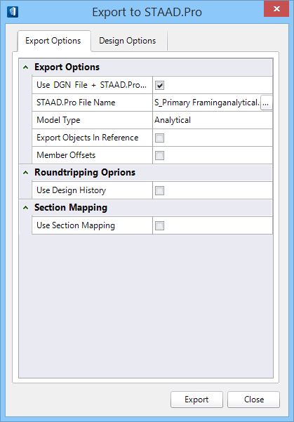
Export Options
tab
| Setting | Description |
|---|
| Export Options
|
- Use DGN
File + STAAD.Pro Extension - When on, the exported file is
automatically named using the DGN file name and the
*.std file extension. When off, you can
browse for your
*.std file name and location.
- STAAD.Pro
File Name - Displays the exported
*.std file name. When enabled, user
defined files can be selected by clicking the browse button
[...].
- Model
Type - Selects either the
Analytical or
Physical structural model for export.
Analytical exports the analytical model,
and operates on the analytical members in the active DGN only.
Physical exports the physical model, and
operates on all physical members, including those without analytical member
associations. Selecting
Physical as the model to export enables
the
Export Objects in Reference option.
- Export
Objects in Reference - When on, physical members in reference
attachments are also exported. This option is only enabled if the physical
model is exported.
Note: If
referenced analytical members are detected, they are scanned and the
information passed through the translator.
- Member
Offsets - When on, member offsets or cutbacks are exported.
|
| Roundtripping Options
|
Contains
revision tracking controls to specify
OpenBuildings Station Designer's actions after
you export structural data from
OpenBuildings Station Designer to STAAD.Pro.
- Use
Design History — When on, Design History is used to track
revisions. When off, Design History is not used.
|
| Section Mapping
|
Contains controls used to activate and specify
Section Mapping between
OpenBuildings Station Designer and
STAAD.Pro.
|
| Export
|
Exports the data to a file that can be used by
STAAD.Pro.
|
| Close
|
Closes Export to STAAD.Pro without exporting.
|
Key-in:
mdl
load Bentley.Building.Structural.staadTools.dll Export